The CMRR's release notes for their MB-EPI sequence recommend using the 32-channel head coil for multiband EPI, and they caution against using the 12-channel head coil:
"The 32-channel Head coil is highly recommended for 3T. The 12-channel Head Matrix is not recommended, but it can be used for acceptable image quality at low acceleration factors."
But what does "low acceleration" mean in practice? And what if your only choice is a 12-channel coil? Following a couple of inquiries from colleagues, I decided to find out where the limits might be.
Let's start by looking at the RF coil layout, and review why the 12-channel coil is considered an inferior choice. Is it simply fewer independent channels, or something else? The figure below shows the layout of the 12-ch and 32-ch coils offered by Siemens:
 |
| From Kaza, Klose & Lotze (2011). |
In most cases, the EPI slice direction will be transverse or transverse oblique (e.g. along AC-PC), meaning that we are slicing along the long axis of the magnet (magnet Z axis) and along the front-to-back dimension of the head coil. Along the long axis of the 12-ch coil there is almost no variation in the X-Y plane. At the very back of the coil the loops start to curve towards a point of convergence, but still there is no distinction in any direction in the X-Y plane. Compare that situation to the 32-ch coil. It has five distinct planes of coils along the Z axis. With the 32-ch coil, then, we can expect the hardware - the layout of the loops - to provide a good basis for separating simultaneously acquired axial slices, whereas there is no such distinct spatial information available from the coil elements in the 12-channel coil. In the 12-channel coil, every loop detects a significant and nearly equal fraction of any given slice along Z.
There is an additional complication for the Siemens 12-channel coil. It is what Siemens call a "Total Imaging Matrix (TIM)" coil. This means that, depending on a software setting, the signals from the twelve loops can be combined in ways that can lead to better receive-field heterogeneity, or higher SNR, or the whole ensemble can be left as an array coil. The maximum amount of receive field heterogeneity is produced from the "Triple" mode, so that's what I'll use here.
Modern simultaneous multi-slice (SMS) sequences use a scheme called blipped CAIPI to assist in the separation of slices at the reconstruction stage. I've not found a didactic review that can get you up to speed on this method. (If you find one, please post a link in the comments!) The original paper by Setsompop et al. is about as accessible as I've found. For now, a brief summary should suffice. The figures below may or may not help you understand what's going on without reading the full paper!
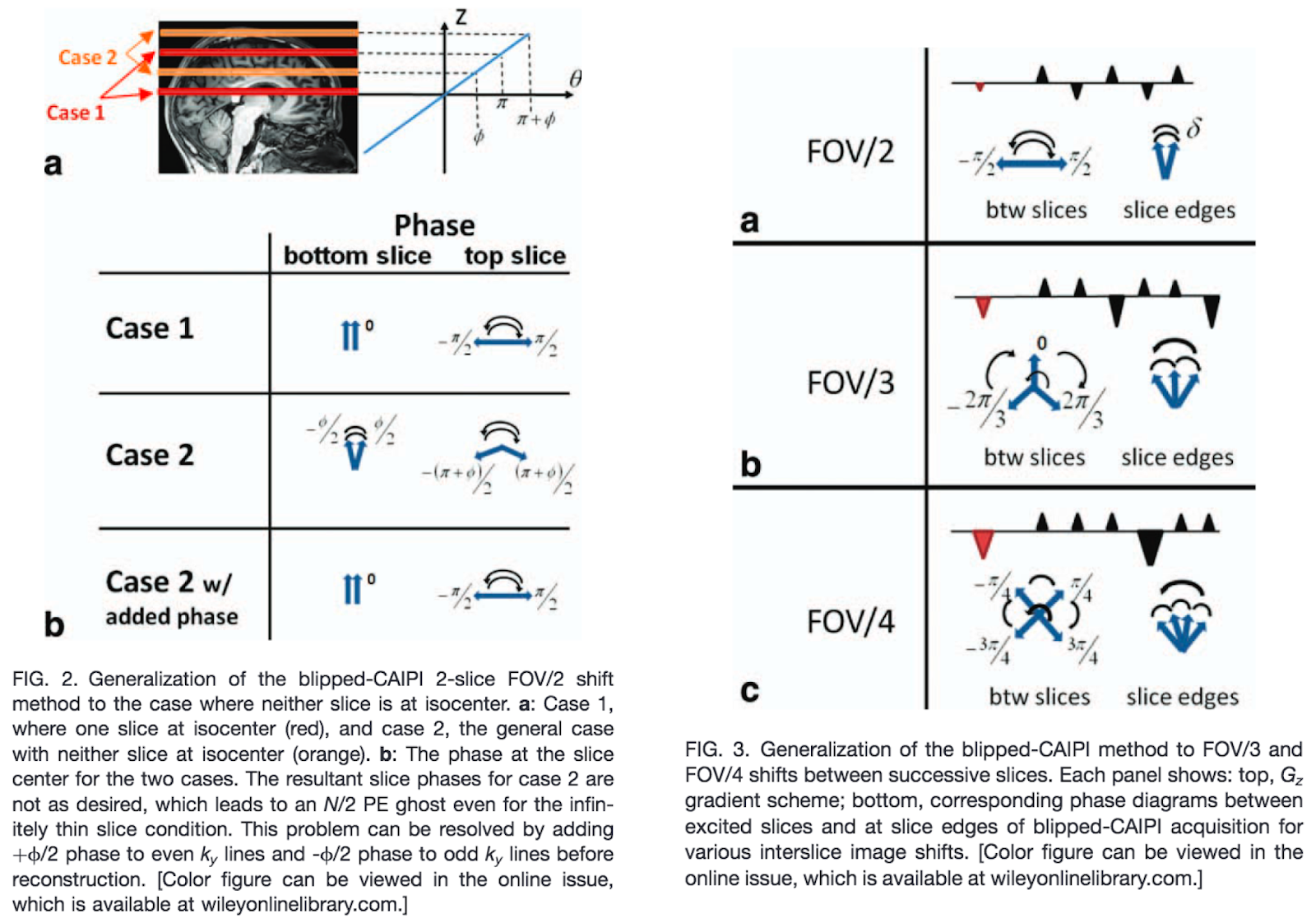 |
| From Setsompop et al. (2012). |
The essential idea is to add a small amount of phase shift along the slice dimension, using small gradient episodes that look very similar to the blips used for phase encoding in-plane. Unlike the phase encoding blips, which are set to be fully refocused - zero net phase shift - at TE, with the blipped CAIPI scheme the phase is designed to refocus every two, three or four lines of k-space. The phase shift is designed to move the image in the field-of-view (FOV) by half, one third or one quarter of the FOV, respectively. But because the blipped CAIPI gradient is active along the slice direction, slices which differ in their Z offset will accrue a differing amount of total shift. This has the effect of encoding unique spatial information in two slices that differ in Z. Importantly, we have imparted a phase shift to the slices in deterministic fashion, meaning that we can then account for that shift at the processing phase, and return the signal to its correct location in the FOV once the slice separation procedure has been performed.
What are the implications for doing MB-EPI on a 12-channel instead of a 32-channel coil? We've already seen there is considerable unique spatial information available along the Z axis from the coil geometry in the 32-channel coil. While blipped CAIPI may improve MB slice separation, it's not being relied upon to do all the work with the 32-ch coil. The hardware carries a lot of the burden. But with the 12-channel coil, the hardware offers almost no support at all. In that case, the work of separating slices is going to rely heavily on the blipped CAIPI scheme. We are fixing it in software, not hardware, as the old engineering joke puts it.
Phantom tests
Time to test it out in practice. The 32-channel coil offers our performance standard. The idea is to keep everything constant and vary only the receive coil, and compare. But what parameters to test? We can expect performance to drop off quickly as the MB factor goes up. While I have tested MB=6 with the 32-channel coil in an earlier blog post, in practice I generally don't like using greater than MB=5, to match the number of planes of independent coil loops in the axial direction. But let's not run before we can walk. Compared to no slice acceleration, a shift to MB=2 is already an impressive gain in speed on a 12-channel coil. To keep things reasonable I tested MB=2 and MB=3 first, deciding that I would only opt for larger MB factors if these tests suggested there is even more performance available. (tl;dr the limit is between 2 and 3, no further tests are forthcoming!)
Spatial resolution is the next consideration. In the absence of acceleration, we are generally limited to voxel dimensions of about 3.5 mm if we want to cover the majority of cortex in a TR of 2 seconds. Here, I decided to push to voxel dimensions of 2.5 mm, leaving the TR at 2 seconds. It's entirely permissible to take the TR reduction offered by MB without changing the voxel dimensions, of course, but I'm primarily interested in the generation and avoidance of artifacts, not the speed limit. The increased resolution in-plane makes the gradients work harder, may require partial Fourier to keep the TE reasonable, and is generally likely to trigger artifacts largely independent of the TR.
I used a spherical gel phantom (the FBIRN phantom) in the first set of comparisons. The slices were axial. An oblique axial prescription - say, AC-PC - is only likely to improve performance, since there is some unique coil information available by the time the slice direction is coronal (slices along the Y axis of the magnet). But I didn't have time to test this theory out.
Here are the tests:
- MB=2, (2.5 mm)³ voxels, with Leak Block
- MB=2, (2.5 mm)³ voxels
- MB=3, (2.5 mm)³ voxels, with Leak Block
- MB=3, (2.5 mm)³ voxels
- MB=1, (2.5 mm)³ voxels, Interleaved slice order
I kept TR constant at 2000 ms throughout, and acquired 100 volumes for each test. Prescan normalization was enabled (with raw data also saved) for the 32-channel coil, but was disabled for 12ch and neck coils. See here, here and here for more information on the use of Prescan Normalization with receiver coils exhibiting pronounced receive field heterogeneity.
The 32-channel coil - our performance benchmark - produced good results consistently, as expected. I'm showing three views of the phantom data: 1. the in-plane dimension contrasted for the signal, 2. the in-plane dimension contrasted for ghosting and noise, and 3. the slice dimension reconstructed from the stack of slices. This will be the order for all comparisons to come. To keep the comparisons vaguely manageable, here I've omitted the MB=1 images from the 2x2 views. (You can find a bonus set of comparisons that includes MB=1 for the 32-channel coil in Note 1.)
 |
| 32-channel coil, contrast set for visualization of signal. Phase encoding direction top-to-bottom, frequency encoding direction L-R. |
 |
| 32-channel coil, contrast set for visualization of ghosts and noise. Phase encoding direction top-to-bottom, frequency encoding direction L-R. |
 |
| 32-channel coil, contrast set for visualization of signal. Slice direction top-to-bottom, frequency encoding direction L-R. |
As we should expect, MB=3 generates slightly more (and differently patterned) residual aliasing artifacts compared to MB=2, but these are visible only in the noise-contrasted view. The intensity is sufficiently weak that the artifacts aren't visible on the signal-contrasted views of the in-plane or the slice dimensions.
Here are the results for the 12-channel coil, with the contrast settings and 2x2 image layout as above:
 |
| 12-channel coil, contrast set for visualization of signal. Phase encoding direction top-to-bottom, frequency encoding direction L-R. |
 |
| 12-channel coil, contrast set for visualization of ghosts and noise. Phase encoding direction top-to-bottom, frequency encoding direction L-R. |
 |
| 12-channel coil, contrast set for visualization of signal. Slice direction top-to-bottom, frequency encoding direction L-R. |
If you look very carefully, you can see some artifacts overlapping the phantom in the signal-contrasted views for both the in-plane and slice dimensions for MB=3, whether using Leak Block or not. There are no such artifacts visible for the MB=2 data, however. It appears that we've found the performance threshold. Clearly, the artifact level would only increase for MB factors above 3. Is MB=3 usable? I would be inclined to use MB=2 without much reservation, but I would want to do many more tests with MB=3 before I commit. So let's take a look at the performance on a live human brain.
Brain tests
For the brain tests, I left all acquisition parameters as for the phantom data. Unlike the phantom, however, we now have considerable image contrast variations as well as the potential for movement. I didn't have time to acquire time series measurements for temporal SNR (tSNR) assessments, I'm afraid, so all I can offer is static views in which I've tried to pick the strongest examples of any artifacts I could find. It's not perfect, but it gives us a crude assessment.
The data obtained on the 32-channel coil are our standard:
 |
| 32-channel coil, contrast set for visualization of signal. Phase encoding direction top-to-bottom, frequency encoding direction L-R. |
 |
| 32-channel coil, contrast set for visualization of ghosts and noise. Phase encoding direction top-to-bottom, frequency encoding direction L-R. |
 |
| 32-channel coil, contrast set for visualization of signal. Slice direction top-to-bottom, frequency encoding direction L-R. |
The residual aliasing levels are comparable for both MB=2 and MB=3, with and without Leak Block. So now let's check the performance of the 12-channel coil:
 |
| 12-channel coil, contrast set for visualization of signal. Phase encoding direction top-to-bottom, frequency encoding direction L-R. |
 |
| 12-channel coil, contrast set for visualization of ghosts and noise. Phase encoding direction top-to-bottom, frequency encoding direction L-R. |
 |
| 12-channel coil, contrast set for visualization of signal. Slice direction top-to-bottom, frequency encoding direction L-R. |
As in the phantom, the residual aliasing is higher for MB=3 than for MB=2. But the artifact level is low and is only visible in the ghost-contrasted scan. There is no obvious banding artifact or residual aliasing overlapping signal regions. And, as on the phantom, Leak Block seems to make little difference.
Based on these initial tests, I would conclude that MB=2 is quite reasonable to use on the 12-channel coil, and MB=3 might be considered after a couple more tests, especially tSNR tests and artifact evaluations in the presence of subject motion.
MB-EPI on a neck coil
A few of us are interested in non-human imaging, e.g. using a neck coil for dog fMRI, or for scanning sea lion brains, like this:
 |
| Using the (human) neck coil to scan Cronut, a 3 year-old male California sea lion. |
I reproduced the tests above to find out if the neck coil might be used for MB-EPI. You can see in the images below that the receive profile of the neck coil drops off quite quickly front and back. For humans, the usual procedure is to have the neck coil on the bed along with the 12-channel head coil, allowing a considerable boost of the receive field in one direction. But that's an experimental detail not directly related to the evaluation of MB-EPI. It is something to note if you are trying to position dog or sea lion brains in the most sensitive part of the coil.
You're familiar with the parameters and the layout of the final images by now. Here are the comparison images for MB=2 and MB=3, with and without Leak Block:
 |
| Neck coil, contrast set for visualization of signal. Phase encoding direction top-to-bottom, frequency encoding direction L-R. |
 |
| Neck coil, contrast set for visualization of ghosts and noise. Phase encoding direction top-to-bottom, frequency encoding direction L-R. |
 |
| Neck coil, contrast set for visualization of signal. Slice direction top-to-bottom, frequency encoding direction L-R. |
There are clear artifacts in the MB=3 acquisitions, and Leak Block doesn't help. There are also subtle artifacts visible in-plane but not obviously in the slice direction for the MB=2 data. The artifact level is worse than for MB=2 on the 12-channel coil, but lower than that for MB=3 on the 12-channnel coil. Based on these results, I would avoid using MB=3 on the neck coil, but I would be tempted to use MB=2 if the particular application called for it.
I'm afraid I don't have live sea lion brain data to show so I'm using the next best thing - a live human. I tested only MB=2 on the grounds that the phantom data for MB=3 weren't encouraging. I may go back and test MB=3 on a human at a later date. For now, I am comparing the MB=2 performance to the single band reference (SBRef) images acquired at the start of a run. These SBRef images are acquired with a different effective TR, that is, at an effective TR of (TR x MB), so the T₁-weighted contrast is quite different. Still, these images provide a reasonable basis for evaluating SMS artifacts:
 |
| Neck coil, contrast set for visualization of signal. Phase encoding direction top-to-bottom, frequency encoding direction L-R. |
 |
| Neck coil, contrast set for visualization of ghosts and noise. Phase encoding direction top-to-bottom, frequency encoding direction L-R. |
 |
| Neck coil, contrast set for visualization of signal. Slice direction top-to-bottom, frequency encoding direction L-R. |
Not too bad. No obvious artifacts are visible in any of the MB data, confirming that use of MB=2 is likely permissible for the neck coil.
In the next post, I'll look at MB-EPI for diffusion imaging on the same three coils.
_______________________
Notes:
1. Here is a bonus set of comparisons for the MB=2 tests, for the 12-channel and neck coils compared to both MB=2 and MB=1 with the 32-channel coil. The MB=2 and MB=1 data quality is quite similar for the 32-channel coil, except that the slice coverage is much reduced for MB=1.
 |
| Phase encoding direction top-to-bottom, frequency encoding direction L-R. Leak Block used for MB=2. Contrast set for visualization of signal. |
 |
| Phase encoding direction top-to-bottom, frequency encoding direction L-R. Leak Block used for MB=2. Contrast set for visualization of ghosts and noise. |
 |
| Slice direction top-to-bottom, frequency encoding direction L-R. Leak Block used for MB=2. Contrast set for visualization of signal. |
Thanks, this is really useful. Do you have any comments on using the Prisma 20-channel head(16)/neck(4) coil for brain imaging. The 32-channel is too tight for many individuals. In 06/2016 you mention you hoped to evaluate the 20 channel coil. I do not know the configuration of the 20-channel coil, but it would be nice to know reasonable SMS/iPAT settings for this popular coil.
ReplyDeleteI don't know the layout of that coil either, and I don't have convenient access to a Prisma to look or to test with MB. I can't imagine it being any worse than the 12ch on the Trio. With luck someone who has a Prisma will be motivated to test it and let us know!
DeleteSample 20 channel (MB=2,3,4,5) and 32 channel (MB=2,5) from a human volunteer and 100 volumes are provided here: https://osf.io/q4d53/
ReplyDeleteI would be interested in any thoughts.